Download this Case Study:
Introduction:
The rise in total generation capacity of renewable energy sources such as wind and solar is resulting in traditional “base load” fossil generation plants being more frequently asked to follow fluctuating electricity demand, i.e. “peak load” operation. This change in operation has a consequential effect on power plant equipment, as it is now being subjected to operating conditions it was not originally designed for.
In a previous paper entitled Effects of changing plant operational modes on Boiler Water Circulating Pumps, a general level overview of all the damage mechanisms associated with this type of operation were discussed. Recent operating experience of plants has shown that excessive thrust damage has been occurring. This thrust damage is the result of the suction pressure to the pump dropping below the water vapor pressure, causing steam flashing in the pump.
The scenario is most prominent when the plant changes load quickly or has a trip. Graph 1 shows an example of such a case where a sub-critical power plant experienced an unexpected trip. As can be seen in the graph, the plant load is sitting around 200MW (shown on the right-hand axis) when an unexpected event occurs. The plant load drops to 0MW, and subsequently the drum pressure begins to drop. During this time, the BWCP continues to operate.
Graph 1: Plant trip scenario #1
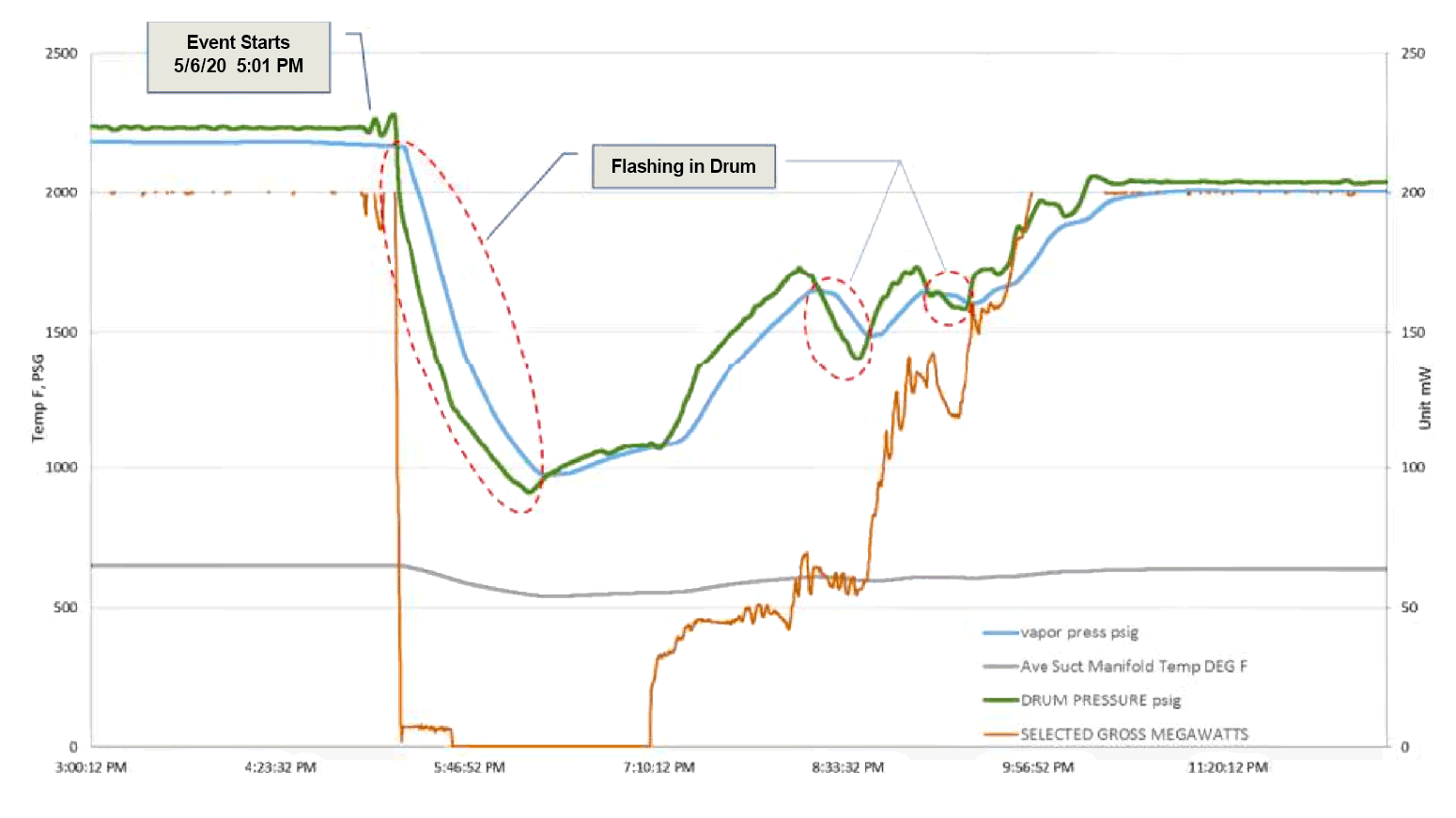
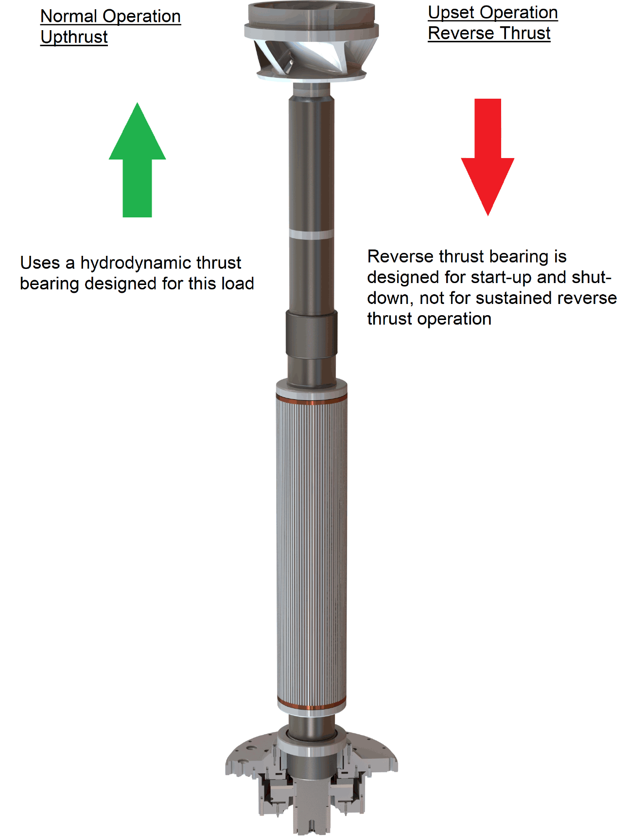
The drum pressure (green line) drops below the vapor saturation pressure (blue line), which results in the pump suction experiencing vapor. A loss of hydraulic lift causes the rotor to drop and then run on the reverse thrust bearing, which was not designed for this operation mode.
This scenario has been observed not only during trip scenarios, but during regular load changes as well.
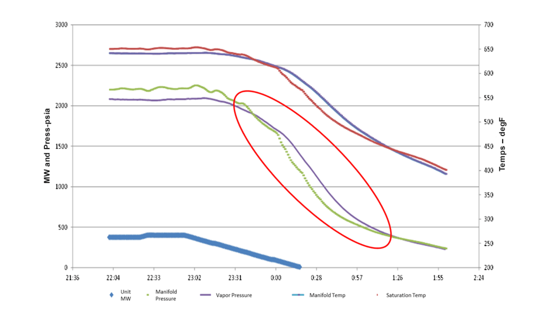
This can be observed in Graph 2 during a routine plant shutdown. The plant can be seen to reduce load steadily (blue line). During this time, it can be observed that the manifold pressure (green line) drops below the boiler water vapor pressure. This results in vapor being present at the pump inlet.
Graph 2: Boiler shutdown scenario showing vapor information
Unbalanced forces across the impeller
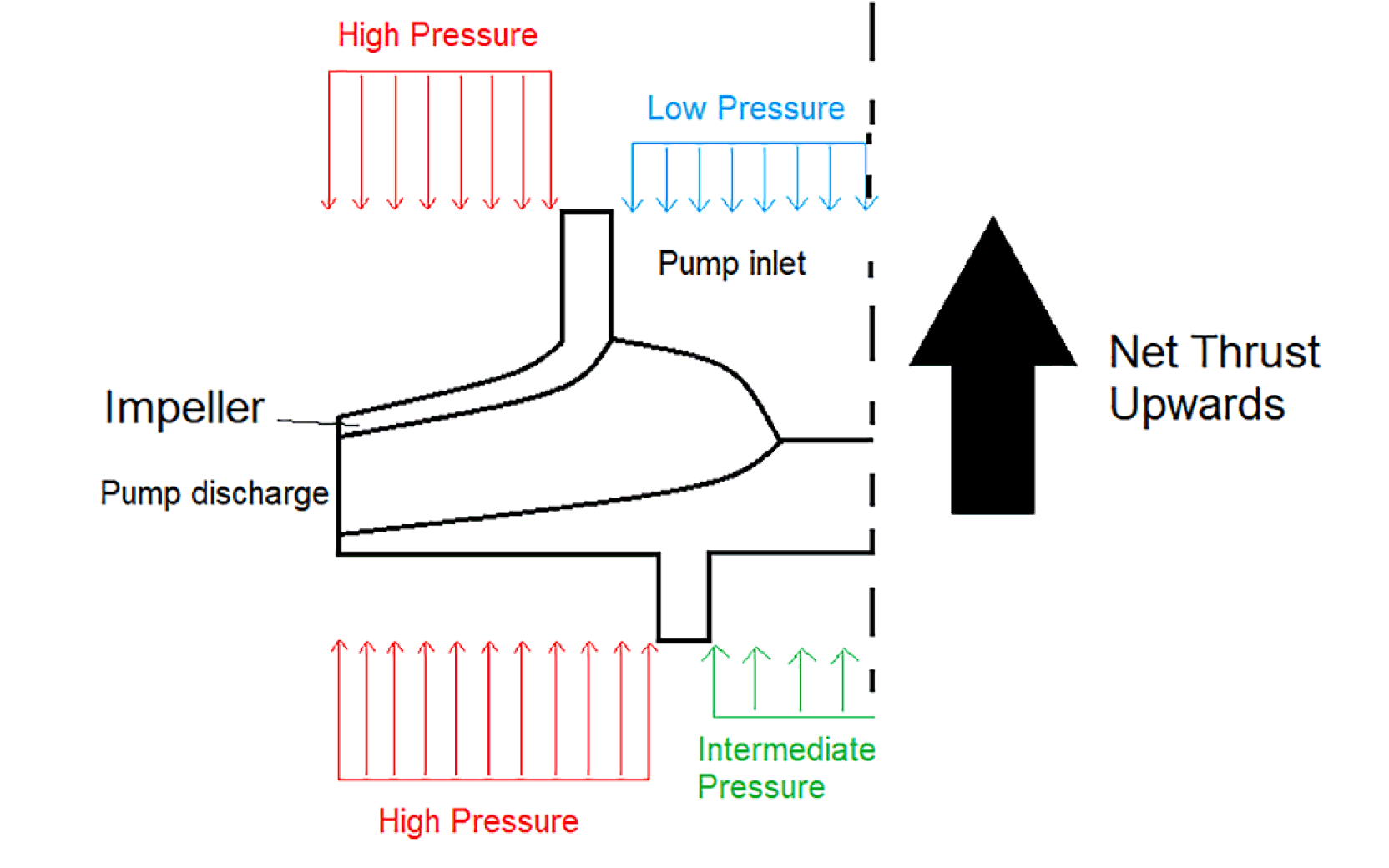
The majority of BWCPs used on drum boilers use a single direction thrust bearing. The thrust bearing is designed to accommodate the weight of the rotating assembly, along with the thrust load that is generated by the impeller. The impeller rotating in the liquid produces a centrifugal effect, creating pressure in the fluid. The unequal distribution of pressure between the front and back shrouds of the impeller creates an upwards thrust.
This is shown below in Figure 1, with the pressure exerted on the different pump surfaces due to the energy imparted on the pump liquid, creating the net upward thrust.
Figure 1: Pressure distribution across impeller
When steam passes through the impeller in place of the water, the discharge pressure, and hence differential pressure, is much smaller. This results in the rotor weight overcoming the thrust being produced by the impeller and the rotating assembly running against the reverse thrust bearing. The two scenarios are shown below in Figure 2.
Figure 2: Rotating assembly showing thrust scenarios
Bearing configuration
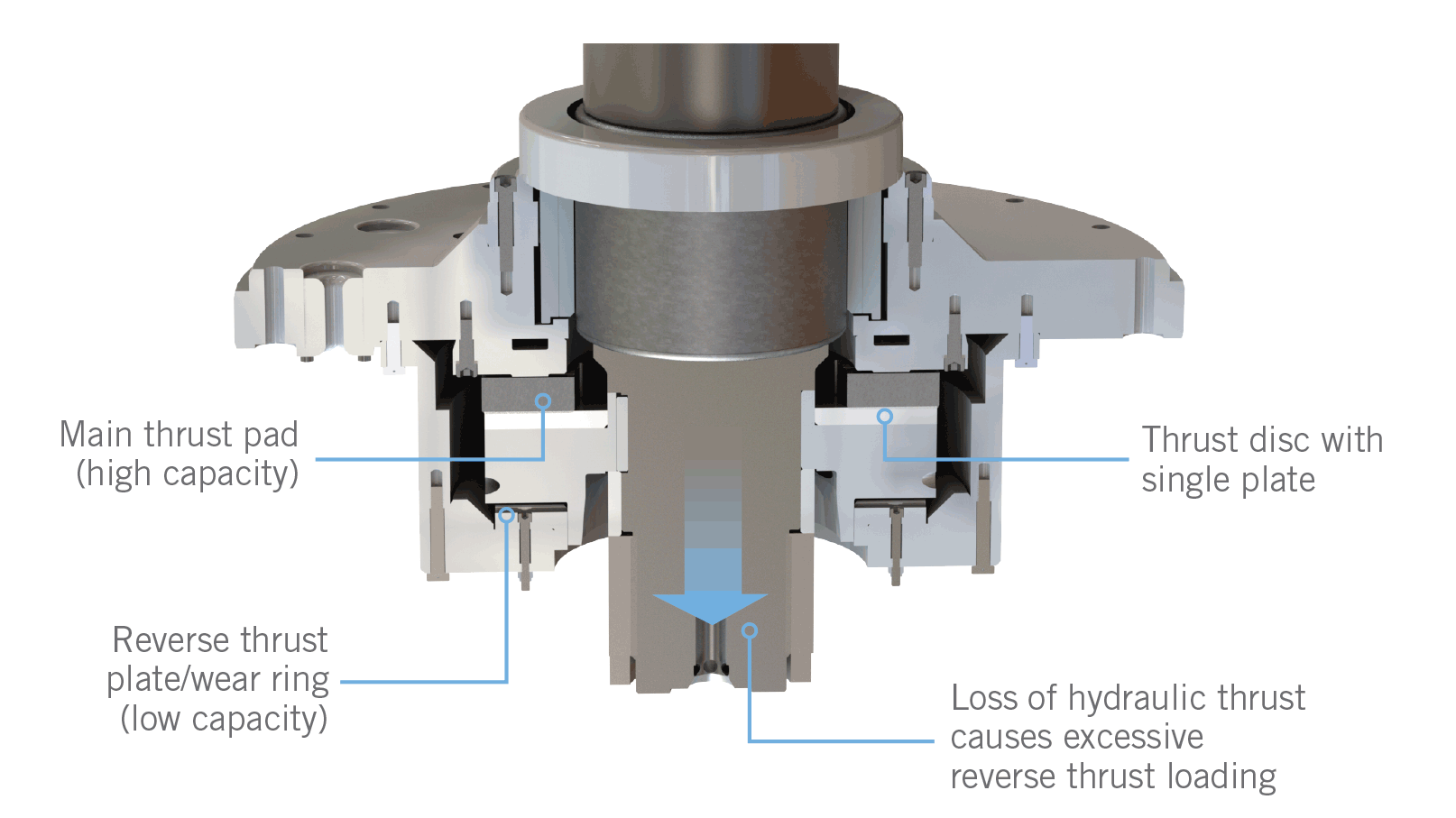
The reverse thrust direction uses a reinforced polymer thrust plate (reverse thrust plate/wear ring) running against a steel thrust disc. This configuration is designed for intermittent service during start-up and shutdown. If operated correctly, this provides satisfactory service life, which has been demonstrated over the past 50 years. This design does not use a hydrodynamic film, and therefore, when operated in a continuous manner in the reverse thrust direction, it can cause rapid wear and, eventually, premature failure.
Figure 3 below shows an annotated single thrust design highlighting the main and reverse bearing configuration, along with the direction of rotor movement due to lost hydraulic lift.
Figure 3: Single thrust bearing configuration
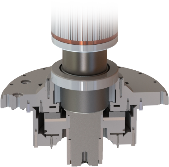
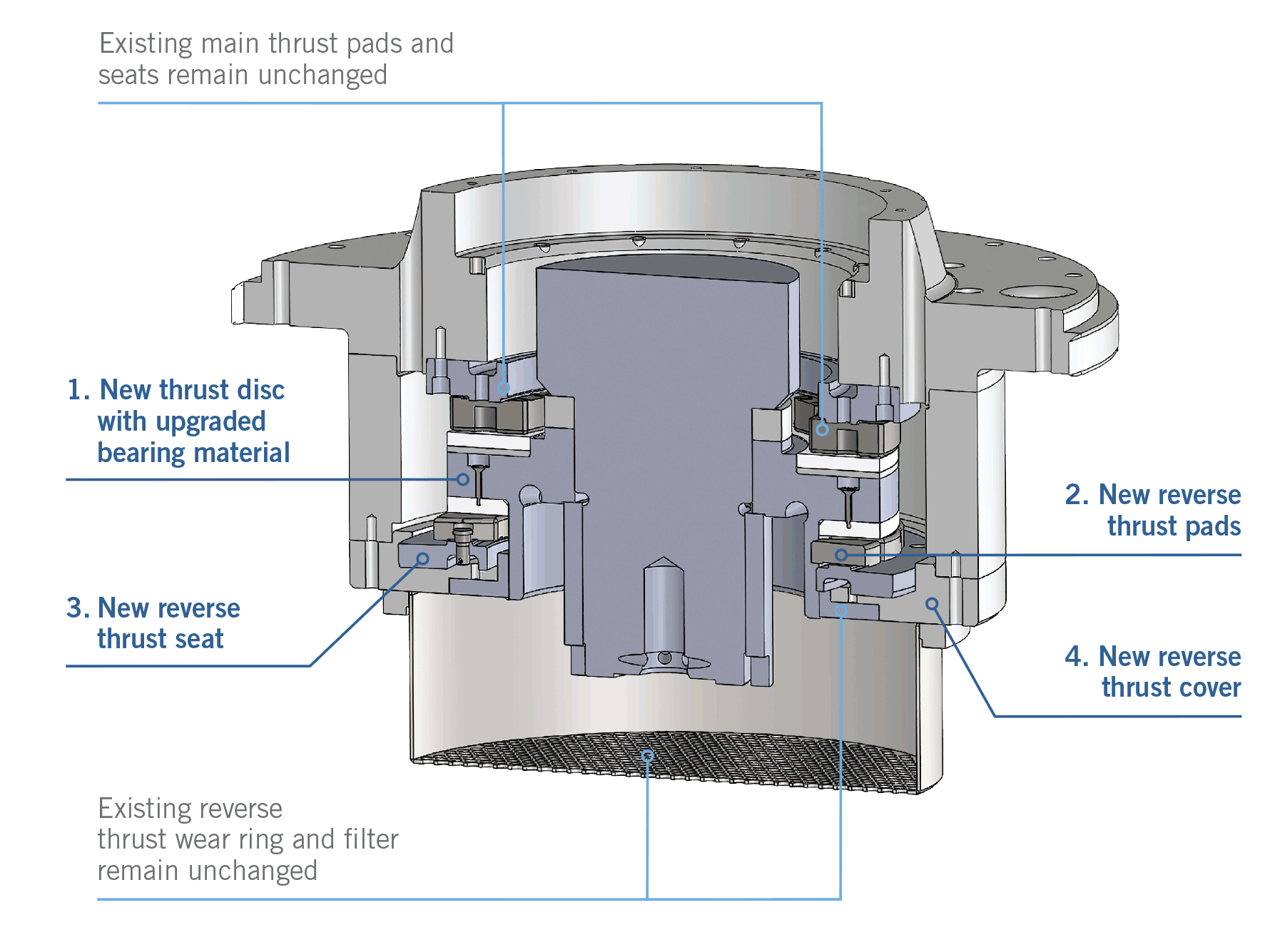
Recognizing this problem is often associated with the necessary flexibility plants must provide, Hayward Tyler has designed a double thrust bearing upgrade for existing single thrust bearing BWCPs. This upgrade replaces the reverse thrust plat/wear ring with a thrust bearing similar to the main thrust. This can be seen in Figure 4.
Figure 4: Double Thrust upgrade
Categories: White Papers


